Next: VI. Monitor Units Up: 25. Radiative Transfer Unit Previous: 25. Radiative Transfer Unit Contents Index
The radiative transfer (25.1) and electron energy
(25.2) equations can be simplified using a multigroup
diffusion approximation. The frequency space is divided into ![]() groups with
groups with ![]() . Group
. Group ![]() is defined by the frequency range
from
is defined by the frequency range
from ![]() to
to ![]() . The plasma is assumed to emit radiation
in a Planck spectrum with a given emission opacity. The multigroup
diffusion equations solved by FLASH are
. The plasma is assumed to emit radiation
in a Planck spectrum with a given emission opacity. The multigroup
diffusion equations solved by FLASH are
 |
(25.5) |
The multigroup diffusion equation and electron internal energy
equation are operator-split using an explicit treatment. Thus, on each
time step (25.4) is solved for each energy group using
coefficients evaluated at time level ![]() using an implicit treatment
for the diffusion solution itself. The equation below shows how the
multigroup equations are discretized in time
using an implicit treatment
for the diffusion solution itself. The equation below shows how the
multigroup equations are discretized in time
The diffusion equation, (25.6), is an implicit equation and is solved using the general implicit diffusion solver described in section 19.1.2. It is recommended that users familiarize themselves with the general implicit diffusion solver to learn more about using MGD in FLASH.
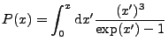
The planck integral in previous versions has significant error and can be
negative for
![]() . Set rt_planckIntMethod to 0
(by default) to use the method in old versions. Set
rt_planckIntMethod to a positive number to use the new method:
mininum of the
. Set rt_planckIntMethod to 0
(by default) to use the method in old versions. Set
rt_planckIntMethod to a positive number to use the new method:
mininum of the ![]() -th order expansion as
-th order expansion as
![]() and the
and the ![]() -th order
expansion as
-th order
expansion as ![]() . Current available options: set to
. Current available options: set to ![]() for
for ![]() and
and
![]() , set to
, set to ![]() for
for ![]() and
and ![]() , set to
, set to ![]() for
for ![]() and
and ![]() .
.
This section describes how to use MGD in FLASH. Section 35.7.5 shows an example of how to use MGD in a realistic HEDP simulation and is extremely informative.
Several setup options are needed to use MGD. The +mgd setup shortcut will include the MGD unit in the simulation. In addition, storage needs to be created for storing the specific energy for each group. This is done using the mgd_meshgroups setup variable. The user must set mgd_meshgroups such that:
| (25.8) |
+mgd mgd_meshgroups=6
The FLASH checkpoint files will contain the specific energy in each
radiation energy group for each cell. The variables are named
r### where ### is a three digit number from one to
![]() . Users can also add these variables to the list of plot
variables so they will be included in plot files.
. Users can also add these variables to the list of plot
variables so they will be included in plot files.
Several runtime parameters are used to control the MGD unit. The
runtime parameter rt_useMGD must be set to .true. for
MGD simulations. The energy group structure (values of the group
boundaries) are specified, manually, using runtime parameters. A
simulation with ![]() groups will have
groups will have ![]() energy group
boundaries. These are set using the rt_mgdBounds_### runtime
parameters, where ### is a number between 1 and
energy group
boundaries. These are set using the rt_mgdBounds_### runtime
parameters, where ### is a number between 1 and ![]() . By
default, enough runtime parameters exist for specifying 101 energy
group boundaries. In the case that more groups are needed, the
mgd_maxgroups setup variable sets the number of group boundary
runtime parameters. For example, if 200 energy groups are needed, then
mgd_maxgroups=200 should be specified on the setup line. If
. By
default, enough runtime parameters exist for specifying 101 energy
group boundaries. In the case that more groups are needed, the
mgd_maxgroups setup variable sets the number of group boundary
runtime parameters. For example, if 200 energy groups are needed, then
mgd_maxgroups=200 should be specified on the setup line. If
![]() , no action is needed.
, no action is needed.
When MGD is in use, the Opacity unit provides opacities for each cell. Thus, the useOpacity runtime parameter must be set to true and the appropriate opacity model must be specified. Please see section 23.5 for a detailed description on how to use the Opacity unit in FLASH.
Finally, the radiation boundary conditions must be specified using
runtime parameters. The parameters:
rt_mgdXlBoundaryType
rt_mgdXrBoundaryType
rt_mgdYlBoundaryType
rt_mgdYrBoundaryType
rt_mgdZlBoundaryType
rt_mgdZrBoundaryType
As was mentioned earlier, FLASH uses the generalized implicit diffusion solver, described in section 19.1.2, to solve (25.6) for each energy group. Thus, users must make sure to include an appropriate diffusion solver in their simulation.
When many energy groups are needed, domain decomposition alone is not an effective method for speeding up calculations. The computation time scales roughly linearly with the number of energy groups. As the number of groups increases, users can divide the mesh among larger number of processors to compensate. This is an effective strategy until the strong scaling limit for the simulation is reached. At this point, mesh replication becomes the only way to speed up the simulation further.
Mesh replication allows FLASH to perform the diffusion solves for each
energy group in parallel. By default, mesh replication is deactivated
and each diffusion equation is solved serially. When mesh replication
is in use the total pool of ![]() processes is divided among
processes is divided among ![]() identical copies of the computational mesh. The radiation solver uses
these copies of the mesh to perform
identical copies of the computational mesh. The radiation solver uses
these copies of the mesh to perform ![]() parallel radiation
solves. The runtime parameter meshCopyCount is used to set
parallel radiation
solves. The runtime parameter meshCopyCount is used to set
![]() and has a value of 1 by default.
and has a value of 1 by default.
This is best illustrated with an example. Suppose ![]() , the total
number of energy groups, is set to 100, and there are
, the total
number of energy groups, is set to 100, and there are ![]() processes available to run the simulation. If meshCopyCount=1,
then
processes available to run the simulation. If meshCopyCount=1,
then ![]() and the computational mesh will not be replicated. This
is FLASH's normal mode of operation: the mesh will be divided into six
pieces and each process will be responsible for one of these
pieces. Each process will also be involved in the solution of the
diffusion equation for all 100 energy groups. If
meshCopyCount=2, then the computational domain will be divided
into three pieces. Two processes will be assigned to each piece. In
other words two groups of three processes will be created. The first
set of three processes will be responsible for solving the diffusion
equations for the odd numbered energy groups. The second set of
processes will solve the diffusion equations for the even numbered
energy groups. Each process only knows about 50 of the 100 groups. In
some cases, this may be substantially faster than the
meshCopyCount=1 approach.
and the computational mesh will not be replicated. This
is FLASH's normal mode of operation: the mesh will be divided into six
pieces and each process will be responsible for one of these
pieces. Each process will also be involved in the solution of the
diffusion equation for all 100 energy groups. If
meshCopyCount=2, then the computational domain will be divided
into three pieces. Two processes will be assigned to each piece. In
other words two groups of three processes will be created. The first
set of three processes will be responsible for solving the diffusion
equations for the odd numbered energy groups. The second set of
processes will solve the diffusion equations for the even numbered
energy groups. Each process only knows about 50 of the 100 groups. In
some cases, this may be substantially faster than the
meshCopyCount=1 approach.
Another benefit of mesh replication is that it reduces the amount of memory needed per process. In the example above, when meshCopyCount=1, each process must store the energy density for all 100 energy groups. Thus, storage must exist for 100 cell centered variables on each process. When meshCopyCount=2, storage is only needed for 50 cell centered variables. The setup variable mgd_meshgroups controls the number of cell centered variables created on process. Thus, when meshCopyCount=2, we can set mgd_meshgroups to 50 instead of 100. As a result, far less memory is used per block.
Whether or not mesh replication is helpful for a particular simulation can only be determined through extensive testing. It depends on the particular simulation and the hardware.
The initial conditions must be specified throughout the domain for
each radiation energy group. This involves setting the specific
energy,
![]() , in units of erg/g for each group. Because
of the mesh replication capability, the user is discouraged from
manually setting the value of the underlying radiation mass
scalars. Instead, several routines have been added to the
RadTrans unit to simplify this process dramatically. Specifying
the initial conditions involves two steps. First, the value of
, in units of erg/g for each group. Because
of the mesh replication capability, the user is discouraged from
manually setting the value of the underlying radiation mass
scalars. Instead, several routines have been added to the
RadTrans unit to simplify this process dramatically. Specifying
the initial conditions involves two steps. First, the value of ![]() must be set for each group in each cell. Second, either the total
specific radiation energy,
must be set for each group in each cell. Second, either the total
specific radiation energy,
![]() , or the radiation
temperature,
, or the radiation
temperature,
![]() , must be set - depending on the
value of eosModeInit. Below, two use cases are described.
, must be set - depending on the
value of eosModeInit. Below, two use cases are described.
The easiest way to set the initial condition is to use a radiation temperature in each cell and to assume that the radiation field is described by a Planck spectrum. The subroutine:
RadTrans_mgdEFromT(blockId, axis, trad, tradActual)
will automatically set the value of ![]() for each group using a given
radiation temperature and assuming a black body spectrum. The
arguments are:
for each group using a given
radiation temperature and assuming a black body spectrum. The
arguments are:
Once RadTrans_mgdEFromT has been used to initialize ![]() ,
either the total radiation specific energy,
,
either the total radiation specific energy, ![]() , must be set or the
radiation temperature for the cell must be specified. When the runtime
parameter eosModeInit is set to “dens_temp_gather”, the
initial radiation temperature must be specified in the variable
TRAD_VAR. When eosModeInit is set to “dens_ie_gather”,
, must be set or the
radiation temperature for the cell must be specified. When the runtime
parameter eosModeInit is set to “dens_temp_gather”, the
initial radiation temperature must be specified in the variable
TRAD_VAR. When eosModeInit is set to “dens_ie_gather”,
![]() must be specified in the variable ERAD_VAR.
must be specified in the variable ERAD_VAR.
The example below shows a segment from a Simulation_initBlock routine from a typical simulation which uses MGD:
do k = blkLimits(LOW,KAXIS),blkLimits(HIGH,KAXIS)
   do j = blkLimits(LOW,JAXIS),blkLimits(HIGH,JAXIS)
      do i = blkLimits(LOW,IAXIS),blkLimits(HIGH,IAXIS)


axis(IAXIS) = i
         axis(JAXIS) = j
         axis(KAXIS) = k


...


! Set the secific energy in each radiation group using a
         ! radiation temperature of 1 eV (11604.55 K):
         call RadTrans_mgdEFromT(blockId, axis, 11604.55, tradActual)


! Set the radiation temperature:
         call Grid_putPointData(blockId, CENTER, TRAD_VAR, EXTERIOR, axis, tradActual)


! Alternatively, we could have set ERAD_VAR using a*(tradActual)**4


enddo
   enddo
enddo
Note that tradActual is used to specify the value of TRAD_VAR.
Specifying the radiation temperature is sufficient for many cases. Alternatively, users can manually specify the radiation spectrum. The subroutine
RadTrans_mgdSetEnergy(blockId, axis, group, eg)
has been created for this purpose. The arguments are:
The example below assumes that the user would like to initialize the
radiation field so that
![]() and all other groups are
initialized to zero energy. Note, that for this example, the user
should obtain the value of
and all other groups are
initialized to zero energy. Note, that for this example, the user
should obtain the value of ![]() , the radiation constant, from the
PhysicalConstants unit. This simulations used
, the radiation constant, from the
PhysicalConstants unit. This simulations used ![]() .
.
do k = blkLimits(LOW,KAXIS),blkLimits(HIGH,KAXIS)
   do j = blkLimits(LOW,JAXIS),blkLimits(HIGH,JAXIS)
      do i = blkLimits(LOW,IAXIS),blkLimits(HIGH,IAXIS)


axis(IAXIS) = i
         axis(JAXIS) = j
         axis(KAXIS) = k


...


! Set the secific energy in each radiation group:
         call RadTrans_mgdSetEnergy(blockId, axis, 1, a*sim_trad**4/sim_rho)
         call RadTrans_mgdSetEnergy(blockId, axis, 2, 0.0)
         call RadTrans_mgdSetEnergy(blockId, axis, 3, 0.0)
         call RadTrans_mgdSetEnergy(blockId, axis, 4, 0.0)


! Set the radiation temperature:
         call Grid_putPointData(blockId, CENTER, TRAD_VAR, EXTERIOR, axis, sim_trad)


! Alternatively, we could have set ERAD_VAR using a*sim_trad**4/sim_rho


enddo
   enddo
enddo
In some cases, it is necessary to alter the radiation spectrum
manually, for example, to add a radiation energy source. In these
cases, it is useful to manually alter the mesh variables which store
the specific radiation energy within each group:
![]() . However, because of mesh replication, altering these variables
requires a different procedure than modifying other mesh variables
(such as the density) in FLASH. The reason is that each process does
not, in general, have access to each
. However, because of mesh replication, altering these variables
requires a different procedure than modifying other mesh variables
(such as the density) in FLASH. The reason is that each process does
not, in general, have access to each ![]() . The procedure for
modifying
. The procedure for
modifying ![]() directly is as follows:
directly is as follows:
! Loop over all cells, set the specific radiation energy to zero:
do lb = 1, nblk
  call Grid_getBlkIndexLimits(blklst(lb),blkLimits,blkLimitsGC)
  call Grid_getBlkPtr(blklst(lb), blkPtr)


do k = blkLimits(LOW,KAXIS), blkLimits(HIGH,KAXIS)
    do j = blkLimits(LOW,JAXIS), blkLimits(HIGH,JAXIS)
      do i = blkLimits(LOW,IAXIS), blkLimits(HIGH,IAXIS)
        blkPtr(ERAD_VAR,i,j,k) = 0.0
      end do
    end do
  end do
  call Grid_releaseBlkPtr(blklst(lb), blkPtr)
end do


! Loop over radiation energy groups:
do gloc = 1, NONREP_NLOCS(rt_acrossMe, rt_meshCopyCount, rt_mgdNumGroups)


! g represents the global energy group number:
  g = NONREP_LOC2GLOB(gloc, rt_acrossMe, rt_meshCopyCount)


! gvar represents the index in the block pointer for group g:
  gvar = MGDR_NONREP_LOC2UNK(gloc)


! Loop over blocks and set the energy density in each group:
  do lb = 1, nblk
    call Grid_getBlkIndexLimits(blklst(lb),blkLimits,blkLimitsGC)
    call Grid_getBlkPtr(blklst(lb), blkPtr)


do k = blkLimits(LOW,KAXIS), blkLimits(HIGH,KAXIS)
      do j = blkLimits(LOW,JAXIS), blkLimits(HIGH,JAXIS)
        do i = blkLimits(LOW,IAXIS), blkLimits(HIGH,IAXIS)


! Set the specific energy in group g:
          blkPtr(gvar,i,j,k) = 1.0e+12


! Make sure to track the total radiation energy in the cell:
          blkPtr(ERAD_VAR,i,j,k) = blkPtr(ERAD_VAR,i,j,k) + &
                                   blkPtr(gvar,i,j,k)
        end do
      end do
    end do
    call Grid_releaseBlkPtr(blklst(lb), blkPtr)
  end do
end do


! Finally, every process needs to know the total specific radiation
! energy. RadTrans_sumEnergy adds up ERAD_VAR across all of the
! meshes:
call RadTrans_sumEnergy(ERAD_VAR, nblk, blklst)


! Call EOS to get a consistent state:
do lb = 1, nblk
  call Grid_getBlkIndexLimits(blklst(lb),blkLimits,blkLimitsGC)
  call Eos_wrapped(MODE_DENS_EI_GATHER,blkLimits,blklst(lb))
end do
The second part of the example loops over the groups. Notice the
strange loop ending index. The NONREP_NLOCS macro computes the
number of groups represented on a given process. To find the actual
group number, ![]() , a call is made to NONREP_LOC2GLOB. Next,
MGDR_NONREP_LOC2UNK is called to get the actual index into the
block pointer which corresponds to group g. Following this is a
fairly standard loop over blocks and cells where the block pointer is
used to modify the specific energy in each group. Notice that we are
keeping a running total of the total specific energy in the cell which
is stored in ERAD_VAR.
, a call is made to NONREP_LOC2GLOB. Next,
MGDR_NONREP_LOC2UNK is called to get the actual index into the
block pointer which corresponds to group g. Following this is a
fairly standard loop over blocks and cells where the block pointer is
used to modify the specific energy in each group. Notice that we are
keeping a running total of the total specific energy in the cell which
is stored in ERAD_VAR.
Finally, we must call RadTrans_sumEnergy to add up ERAD_VAR across all of the meshes. After this call, every process will contain the same total specific energy in each cell. This is followed by a call to the equation of state. This is needed to update the radiation temperature and pressure, TRAD_VAR and ERAD_VAR, respectively.
![$\displaystyle \frac{1}{c} \frac{\partial u_g}{\partial t} - \nabla \cdot \left(...
... u_g = \sigma_{e,g} a T_e^4 \frac{15}{\pi^4} \left[ P(x_{g+1}) - P(x_g) \right]$](img2463.png)
![$\displaystyle {}
\frac{1}{c} \frac{\partial u_e}{\partial t} =
\sum_g \left\{ \...
...igma_{e,g} a T_e^4 \frac{15}{\pi^4} \left[ P(x_{g+1}) - P(x_g) \right] \right\}$](img2464.png)
![$\displaystyle \frac{1}{c} \frac{ u_g^{n+1} - u_g^n}{\Delta t} - \nabla \cdot \l...
...gma_{e,g}^n a (T_e^n)^4 \frac{15}{\pi^4} \left[ P(x_{g+1}^n) - P(x_g^n) \right]$](img2473.png)
![$\displaystyle {} \frac{u_e^{n+1}-u_e^n}{\Delta t} = \sum_g \left\{ \sigma_{a,g}...
...^n a (T_e^n)^4 \frac{15}{\pi^4} \left[ P(x_{g+1}^n) - P(x_g^n) \right] \right\}$](img2474.png)