Subsections
The Thomson scattering unit including ray tracing and deflection is a detector driven unit, meaning that
the outer loop is over all Thomson detectors specified. Since for each detector there is only one associated
laser, the code checks whether the associated laser is currently active and if it is, this laser/detector
pair is being processed. The inclusion of ray deflection in a Thomson scattering code presents some
computational challenges. The main difficulty that arises is that the Thomson scattering interaction
region (IR) from where the spectra will be accumulated, is not known beforehand, but must be established
in a first pass through the ray tracing procedure. For each laser/detector pair, the ray tracing Thomson
scattering code consists of two main sections during each time step of the simulation: 1) determination of
the interaction region and 2) assembling the Thomson spectra. Both sections require a complete laser/detector
ray tracing procedure over the entire set of both laser and detector rays. In what follows we will describe
each section separately.
Per definition, the interaction region (IR) consists of those cells of the domain that will have both: 1) incoming
laser (I, from incident) rays and 2) emerging detector (S, from scattered) rays. Each of these so called
IR cells contribute to the final spectrum. In order to find all the IR cells for a specific laser/detector
pair, the complete set of rays for both the laser and the detector are launched towards the domain and
the cells on which both sets intersect will be identified as IR cells. Both laser and detector rays are
launched statistically from their corresponding lenses and towards their target areas. Ray creation, specification
and storage follow much the same way as presented for the EnergyDeposition unit in chapter
18.4.7. Setup of laser/detector beams and pulses are also done as presented in chapters
18.4.6 and 18.4.5. If no Ray deflection is specified and both laser
and detector beams are cylindrical in shape, the resulting set of IR cells are contained in a region
resembling a Steiner solid, i.e. the space obtained from two intersecting cylinders. Ray deflection
usually broadens up the IR region and there can be even cases in which the set of IR cells within
the IR region is not connected, for example if the number of rays used for the laser and the detector is
very low. The user must therefore make sure that the resulting IR region is dense by launching enough
rays from the laser and the detector. On the other hand, as we will see below, assembling the Thomson
spectrum from the set of each IR cell's laser (I) and detector (S) rays is a multiplicative task in
which each I-ray is allowed to scatter into all S-rays. There is hence a delicate balance as to how
many rays are lauched and the size of the intended IR region for computations to remain manageable.
The identification of each IR cell is done by introducing extra two counting cell variables ICNT (for laser)
and SCNT (for detector) into the UNK array (see chapter 6.1). ICNT and SCNT are
incremented by +1 whenever a laser or detector ray hits the cell. After the complete sets of laser and detector
rays have been processed through the domain, the IR cells are those for which both ICNT and SCNT are  0.
Once an IR cell has been identified, its ICNT value is overwritten by its unique tag, which will serve
both as a counting index as well as identifying this cell as an IR cell (for example, for visualization purposes)
in the domain.
0.
Once an IR cell has been identified, its ICNT value is overwritten by its unique tag, which will serve
both as a counting index as well as identifying this cell as an IR cell (for example, for visualization purposes)
in the domain.
During identification of the IR cells, the laser rays will not be allowed to deposit energy in the
domain, as this will change subsequent ray tracing for the same laser/detector pair as well as other
still to be processed laser/detector pairs. Also power loss by both laser and detector rays is not done
at this stage.
Using maximum sized array dimension information from the interaction region finding step, storage arrays
are allocated that will hold detailed info about each I-ray and S-ray for each IR cell. The complete set
of laser and detector rays for the current laser/detector pair is retraced through the domain, this time
all the laser and detector ray info (like direction components of each ray, current power and distance
travelled inside each IR cell) as well each IR cell info (like number electron density, electron
and ion temperature, etc.) is stored for subsequent assembly of the spectra. This time each ray is allowed
to lose power: a laser ray loses absolute power, a detector ray loses relative power starting from
an initial power of 1. The total power loss a ray experiences when travelling from the laser lens to the
detector lens is given by the absolute power loss times the relative power loss, since power is lost
exponentially depending on the time the ray spends in each cell (see Eq.(18.47)).
On each node the local Thomson spectra are assembled by looping over all local IR cells. Each IR cell
contains per definition a set  of incoming laser rays and a set
  of scattered detector rays.
Each laser/detector ray pair (total of
of scattered detector rays.
Each laser/detector ray pair (total of  ) info is now used to determine its contribution to the
local spectrum. Each such pair defines a local IR cell scattering angle as well as a scattering direction.
Together with the info of the local IR cell, a spectrum contribution to all recording frequencies is
calculated using the time-averaged scattered power equation for a collection of charges in the
low-velocity charge (
) info is now used to determine its contribution to the
local spectrum. Each such pair defines a local IR cell scattering angle as well as a scattering direction.
Together with the info of the local IR cell, a spectrum contribution to all recording frequencies is
calculated using the time-averaged scattered power equation for a collection of charges in the
low-velocity charge ( ) limit:
where  is the time-averaged scattered power,
  the scattered frequency,
 the frequency shift between the laser and scattered frequency,
  the incident
laser ray power,
the incident
laser ray power,  the classical electron radius,
  the distance travelled by the ray inside the IR cell,
 the electron number density in the IR cell,
  the detector lens area in steradians,
  the scattering direction unit vector,
 the unit vector along the incident laser electric field,
 the shift in wavenumber between the laser and scattering wave vectors and
 the spectral density function. For an unpolarized laser, the unitless scattering
direction factor
the spectral density function. For an unpolarized laser, the unitless scattering
direction factor
 is averaged over all possible
orientations:
is averaged over all possible
orientations:
where  is the angle between the laser direction and the scattering direction (zero in case of
same direction). If a polarized laser is used, an additional angle
is the angle between the laser direction and the scattering direction (zero in case of
same direction). If a polarized laser is used, an additional angle  between the polarization plane and
the scattering plane is needed, giving:
between the polarization plane and
the scattering plane is needed, giving:
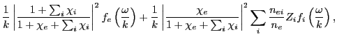
The spectral density function describes how the spectrum
varies in terms of velocity distributions and correlations of the ions with the scattering electrons and
thus contains all the plasma information of the IR cell. Currently only the spectral density function for
an unmagnetized, collisionless, low-temperature plasma containing possibly several ions is implemented:
where  and
and  are the electron and individual ion susceptibilities and
  and the
number of electrons from the i-th ion and the total number of electrons, respectively.
and the
number of electrons from the i-th ion and the total number of electrons, respectively.
 and
and
 are the electron and i-th ion one-dimensional Maxwellian velocity distributions for
the phase velocity
are the electron and i-th ion one-dimensional Maxwellian velocity distributions for
the phase velocity  :
:
with  the Boltzmann constant and
  and
and  the electron (
 ) and ion (
 ) mass and
temperature. Note the two kind
of electron-ion correlation parts in the above
expression: 1) the first term represents
the ion influence on the electron velocity distribution and 2) the second term is the electron influence
on the ions velocity distribution. Derivation of the
expression is involved and the
reader is referred to the literature (Froula et al. 2011, chapters 3 and 5). Since the units of the lhs
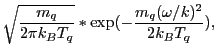
of Eq.(30.1) are power per radial frequency (i.e. power per rad/s), we see that
the units for
must be s/rad, which is also seen from Eq.(30.4),
where the units of
) mass and
temperature. Note the two kind
of electron-ion correlation parts in the above
expression: 1) the first term represents
the ion influence on the electron velocity distribution and 2) the second term is the electron influence
on the ions velocity distribution. Derivation of the
expression is involved and the
reader is referred to the literature (Froula et al. 2011, chapters 3 and 5). Since the units of the lhs
of Eq.(30.1) are power per radial frequency (i.e. power per rad/s), we see that
the units for
must be s/rad, which is also seen from Eq.(30.4),
where the units of  are rad/cm and the units for the velocity distribution functions is s/cm and the
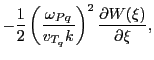
other quantities are dimensionless. The electron and ion susceptibilites are calculated using derivatives
of the plasma dispersion function
are rad/cm and the units for the velocity distribution functions is s/cm and the
other quantities are dimensionless. The electron and ion susceptibilites are calculated using derivatives
of the plasma dispersion function  :
:
where again  represent the electrons or ions,
 is the charge plasma frequency and
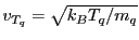 is the RMS thermal velocity of the charge.
 is
the mean thermal velocity normalized phase velocity of the charge, with
is
the mean thermal velocity normalized phase velocity of the charge, with
 .
Details about how to evaluate
.
Details about how to evaluate
 efficiently can again be inferred from
Froula et al. 2011.
efficiently can again be inferred from
Froula et al. 2011.
For higher temperature plasmas, relativistic effects start to get important, but their inclusion into
the scattering equation becomes much more involved. In specific cases it is possible to include
relativistic effects up to first order in  . For example, if the incident Thomson laser is polarized
such that its electrical field
. For example, if the incident Thomson laser is polarized
such that its electrical field  is perpendicular to the scattering plane and if a polarizer
is placed before the detector that only detects scattered fields with electrical field parallel to ,
then it can be shown that Eq.(30.1) needs only be augmented multiplicatively
by the relativistic term:
is perpendicular to the scattering plane and if a polarizer
is placed before the detector that only detects scattered fields with electrical field parallel to ,
then it can be shown that Eq.(30.1) needs only be augmented multiplicatively
by the relativistic term:
| rel.Term |
 |
 |
(30.7) |
This option has been added to the Thomson scattering code, with a default of setting this term
equal to 1 when no relativistic treatment is wanted. The user must however remember that this
relativistic correction applies only under very specific Thomson scattering setups.
After all local spectra contributions have been evaluated, the global contribution to the spectrum
for the current laser/detector pair is calculated and added to the overall Thomson spectrum for the
detector. Writeout to the Thomson detector file is done after the laser for each detector is no longer
active.
30.1.3 Usage
To include the use of the ThomsonScattering unit with ray tracing, the following should be
included into the setup line command:
+ThomsonScatteringWrt thsc_maxPulses=<number> thsc_maxPulseSections=<number>
thsc_maxLaserBeams=<number> thsc_maxDetectors=<number>
- thsc_maxPulses: The maximum number of different laser pulses for the simulation.
- thsc_maxPulseSections: The maximum number of power/time pairs per pulse.
- thsc_maxLaserBeams: The maximum number of Thomson laser beams for the simulation.
- thsc_maxDetectors: The maximum number of Thomson detectors for the simulation.
The ThomsonScattering unit reads all the information it needs to construct the Thomson
scattering environment from runtime parameters specified in the flash.par file. Below is the
list of runtime parameters that is needed to properly set up the Thomson scattering unit.
As the Thomson pulse, laser and detector setup resembles the EnergyDeposition unit pulse and
laser setup, it is encouraged to consult Figures 18.5, 18.6 and
18.7. Both the Thomson laser and the Thomson detector rays are created statistically
on their respective lens and target areas. Regular grids, as for the lasers of the
EnergyDeposition unit, are not supported.
- thsc_numberOfPulses: Controls the number of different Thomson
laser pulses that are going to be used.
- thsc_numberOfSections_n: Gives the number of power/time pairs that
are going to be used to set up the shape of the n-th Thomson laser pulse. There must be at
least as many of these runtime parameters as there are number of Thomson laser pulses defined,
i.e. n = 1,...,thsc_numberOfPulses.
- thsc_power_n_i: Sets the i-th power of the i-th power/time pair of
the n-th Thomson laser pulse. The ranges of the indices must be at
least: i = 1 ,..., thsc_numberOfSections_n and
n = 1 ,..., thsc_numberOfPulses.
- thsc_time_n_i: Sets the i-th time
of the i-th power/time pair of the n-th Thomson laser pulse. The ranges
of the indices must be at least: i = 1 ,..., thsc_numberOfSections_n
and n = 1 ,..., thsc_numberOfPulses.
- thsc_numberOfLaserBeams: The number of Thomson laser beams that are
going to be used.
- thsc_laserCrossSecFuncType_n: Thomson laser beam cross section power
function (flat or gaussian decay) type. For a flat profile use 'uniform', for gaussian decay use
'gaussian2D' (n-th Thomson laser beam).
- thsc_laserGaussCenterMajor_n: The Gaussian center location along the
major elliptical semiaxis (n-th Thomson laser beam).
- thsc_laserGaussCenterMinor_n: The Gaussian center location along the
minor elliptical semiaxis (n-th Thomson laser beam).
- thsc_laserGaussExponent_n: The Gaussian super exponent
 for the
Thomson laser beam cross section power function as presented in equation 18.106
(n-th Thomson laser beam).
for the
Thomson laser beam cross section power function as presented in equation 18.106
(n-th Thomson laser beam).
- thsc_laserGaussRadiusMajor_n: The Gaussian radius (e-folding length)
 along the
major elliptical semiaxis as shown in equation 18.106 (n-th Thomson laser beam).
along the
major elliptical semiaxis as shown in equation 18.106 (n-th Thomson laser beam).
- thsc_laserGaussRadiusMinor_n: The Gaussian radius (e-folding length)
 along the
minor elliptical semiaxis as shown in equation18.106 (n-th Thomson laser beam).
along the
minor elliptical semiaxis as shown in equation18.106 (n-th Thomson laser beam).
- thsc_laserInitialRaySpeed_n: The initial speed of the Thomson laser rays
when hitting the domain boundary, in units of the speed of light (n-th Thomson laser beam).
- thsc_laserLensSAMajor_n: The major (largest) semiaxis length
 for the
laser elliptical lens area (n-th Thomson laser beam).
for the
laser elliptical lens area (n-th Thomson laser beam).
- thsc_laserLensX_n: The x-component of the laser global lens center position
vector
 (n-th Thomson laser beam).
- thsc_laserLensY_n: The y-component of the laser global lens center position
vector (n-th Thomson laser beam).
- thsc_laserLensZ_n: The z-component of the laser global lens center position
vector (n-th Thomson laser beam).
- thsc_laserNoEnergyDeposition_n: If set true, no energy deposition is done
for the Thomson laser rays (n-th Thomson laser beam).
- thsc_laserNumberOfRays_n: Number of statistical Thomson laser rays to be
created for the Thomson laser beam (n-th Thomson laser beam).
- thsc_laserPolarizationAngle_n: Polarization angle (in degrees) of the
incident Thomson laser electrical field with respect to the scattering plane
(cf. Eq.(30.3)). If a negative value is given, the Thomson laser beam is
considered to be unpolarized (n-th Thomson laser beam).
- thsc_laserPulseNumber_n: The pulse shape identification number for the laser
(n-th Thomson laser beam).
- thsc_laserSAMajorTorsionAngle_n: The major elliptical semiaxis torsion angle
 along the Thomson beam's lens target center line (n-th Thomson laser beam).
- thsc_laserSAMajorTorsionAxis_n: The major elliptical semiaxis torsion axis
('x','y' or 'z') from which the torsion angle is defined (n-th Thomson laser beam).
- thsc_laserTargetSAMajor_n: The major (largest) semiaxis length for the
laser elliptical target area (n-th Thomson laser beam).
- thsc_laserTargetSAMinor_n: The minor (smallest) semiaxis length
 for the
laser elliptical target area (n-th Thomson laser beam).
for the
laser elliptical target area (n-th Thomson laser beam).
- thsc_laserTargetX_n: The x-component of the laser global target center position
vector
 (n-th Thomson laser beam).
- thsc_laserTargetY_n: The y-component of the laser global target center position
vector (n-th Thomson laser beam).
- thsc_laserTargetZ_n: The z-component of the laser global target center position
vector (n-th Thomson laser beam).
- thsc_laserWavelength_n: The wavelength (in nm) of the Thomson laser
(n-th Thomson laser beam).
- thsc_numberOfDetectors: The number of Thomson detectors that are
going to be used.
- thsc_detectorLaserBeamNumber_n: The laser beam identification number
associated with the detector (n-th Thomson detector).
- thsc_detectorLensSAMajor_n: The major (largest) semiaxis length for the
detector elliptical lens area (n-th Thomson detector).
- thsc_detectorLensX_n: The x-component of the detector global lens center position
vector (n-th Thomson detector).
- thsc_detectorLensY_n: The y-component of the detector global lens center position
vector (n-th Thomson detector).
- thsc_detectorLensZ_n: The z-component of the detector global lens center position
vector (n-th Thomson detector).
- thsc_detectorNoRayDeflection_n: If set true, the complete set of laser and detector
rays will not be deflected, i.e. all rays will be straight lines. As the ThomsonScattering unit
is detector driven, the detectors decide over the entire ray paths and transmit this info to the associated
laser (n-th Thomson detector).
- thsc_detectorNoRayPowerLoss_n: If set true, the complete set of laser and detector
rays will not experience power loss as they traverse the domain. Useful for comparisons and to see the effect
of the domain on the Thomson spectra (n-th Thomson detector).
- thsc_detectorNumberOfRays_n: Number of statistical Thomson detector rays to be
created for the Thomson detector (n-th Thomson detector).
- thsc_detectorNumberOfSpecPoints_n: Number of spectral points to be recorded
on the Thomson detector (n-th Thomson detector).
- thsc_detectorSAMajorTorsionAngle_n: The major elliptical semiaxis torsion angle
along the Thomson detector's lens target center line (n-th Thomson detector).
- thsc_detectorSAMajorTorsionAxis_n: The major elliptical semiaxis torsion axis
('x','y' or 'z') from which the torsion angle is defined (n-th Thomson detector).
- thsc_detectorScreenSpectralFlux_n: If set true, the output (y-axis) on the detector
will be
 as in Eq.(30.1). If false, the output is in power
 ,
which is
multiplied by the corresponding bin size
,
which is
multiplied by the corresponding bin size
 . One has to be aware that
can sometimes be grossly overestimated, particularly for very narrow Thomson spectra with small widths.
This happens if the recording wavelength window is to broadly set (n-th Thomson detector).
. One has to be aware that
can sometimes be grossly overestimated, particularly for very narrow Thomson spectra with small widths.
This happens if the recording wavelength window is to broadly set (n-th Thomson detector).
- thsc_detectorScreenWavelengths_n: If set true, the horizontal output (x-axis, range of
wavelengths or frequencies) on the detector will be given in wavelengths. If false, the horizontal output is in
frequencies. The wavelength output will have equally spaced tics, while the frequency output will not
(n-th Thomson detector).
- thsc_detectorSkipTimeResolve_n: If set true, the additional time-resolved Thomson
spectra files will not be produced. Only the total Thomson spectra (i.e. without simulation time label) will
be on disk after the simulation. The option of only time-resolved Thomson spectra is not available, meaning
that the total Thomson spectra will always be produced (n-th Thomson detector)
- thsc_detectorTargetSAMajor_n: The major (largest) semiaxis length for the
detector elliptical target area (n-th Thomson detector).
- thsc_detectorTargetSAMinor_n: The minor (smallest) semiaxis length for the
detector elliptical target area (n-th Thomson detector).
- thsc_detectorTargetX_n: The x-component of the detector global target center position
vector (n-th Thomson detector).
- thsc_detectorTargetY_n: The y-component of the detector global target center position
vector (n-th Thomson detector).
- thsc_detectorTargetZ_n: The z-component of the detector global target center position
vector (n-th Thomson detector).
- thsc_detectorUseRelativityTerm_n: If set true, an additional relativistic term
as stated in Eq.(30.7) will be multiplicatively added to the scattered power equation
(30.1). One must be aware, however, that this relativistic term was derived for very
special scattering setups: incident laser electric field is polarized and perpendicular to
the scattering plane and a polarizer is used at the detector to select the scattered radiation electric
field
 to be parallel to . Unless the experimental setup to be simulated does correspond
exactly to this situation, it is best to avoid this term (n-th Thomson detector).
to be parallel to . Unless the experimental setup to be simulated does correspond
exactly to this situation, it is best to avoid this term (n-th Thomson detector).
- thsc_detectorWavelengthMax_n: The maximum recording wavelength (in nm) of the
Thomson detector (n-th Thomson detector).
- thsc_detectorWavelengthMin_n: The minimum recording wavelength (in nm) of the
Thomson detector (n-th Thomson detector).
- thsc_cellTimeEnergyDeposition: If set true, the energy deposition by the
Thomson laser rays is calculated based only on the time spent in each cell by calculating cell
center values of
 and
and  using Eq.(18.46) and replacing the
time integration term in Eq.(18.47) by
using Eq.(18.46) and replacing the
time integration term in Eq.(18.47) by  , i.e. treating as constant
in the cell. If false, the more expensive time integration formalism from Eq.(18.59)
is used.
, i.e. treating as constant
in the cell. If false, the more expensive time integration formalism from Eq.(18.59)
is used.
- thsc_cellWallThicknessFactor: Controls the (imaginary) thickness of the cell
walls to ensure computational stability of the Thomson scattering ray tracing algorithm. The cell
thickness is defined as this factor times the smallest cell dimension along all geometrical axes.
The factor is currently set to a default of
 and should only very rarely be changed.
- thsc_detectorWriteFormatX: Format string for writing out the x-axis data
(wavelengths or frequencies) on the detector screens (default 'es20.10').
- thsc_detectorWriteFormatY: Format string for writing out the y-axis data
(
or
) on the detector screens (default 'es20.10').
- thsc_enforcePositiveNele: (AVG algorithm 18.4.4.1) If true,
the x-, y- and z-components of the gradients
 will be rescaled such that
they always deliver a positive (greater or equal zero) value for the number of electrons in a cell.
will be rescaled such that
they always deliver a positive (greater or equal zero) value for the number of electrons in a cell.
- thsc_enforcePositiveTele: (AVG algorithm 18.4.4.1) If true,
the x-, y- and z-components of the gradients
 will be rescaled such that
they always deliver a positive (greater or equal zero) value for the electron temperature in a cell.
will be rescaled such that
they always deliver a positive (greater or equal zero) value for the electron temperature in a cell.
- thsc_maxRayCount: The maximum number of laser/detector rays that can be
created on one processor. For the Thomson scattering this number must be at least as large as the
maximum over all individual laser and detector sets of rays, i.e. always the entire set of either
the laser or the detector rays for each possible laser/detector pair must fit into memory.
- thsc_printEnergyInfo: If true, it prints info about the Thomson
laser energy entering and leaving the domain (cumulative and at each time step) to a file with name
 basenameThscEnergyProfile.dat, where basename is the base name of the simulation.
- thsc_printLaserBeams: If true, it prints detailed information about the Thomson
laser beams to a file with name basenameThscLaserBeamsPrint.txt, where basename is the base
name of the simulation.
- thsc_printDetectors: If true, it prints detailed information about the Thomson
detectors to a file with name basenameThscDetectorsPrint.txt, where basename is the base
name of the simulation.
- thsc_printMain: If true, it prints general information regarding the Thomson
scattering setup to a file with name basenameThscMainPrint.txt, where basename is the base
name of the simulation.
- thsc_printPulses: If true, it prints detailed information about the Thomson
laser pulses to a file with name basenameThscLaserPulsesPrint.txt, where basename is the base
name of the simulation.
- thsc_printRays: If true, it prints detailed information about all rays
initially generated on each processor to a file(s) with name(s) basenamefileLabelPID.txt,
where basename is the base name of the simulation, fileLabel is a file label name given
by the user and PID is the processor rank number. This runtime parameter should only be used for
debugging purposes (default = false) by developers of the code.
- thsc_printSpecies: If true, it prints detailed information about the species
present in the simulation to a file with name basenameThscSpecies.txt, where basename is
the base name of the simulation.
- thsc_rayDeterminism: If true, the Grid Unit will be forced to use the Sieve
Algorithm to move the ray particle data. Forcing this algorithm will result in a slower movement
of data, but will fix the order the processors pass data and eliminate round off differences in
consecutive runs.
- thsc_rayZeroPower: Below this value (erg/s), the Thomson laser ray is
considered to have zero power.
- useThomsonScattering: If false, the Thomson scattering is not activated,
even if the code was compiled to do so. Bypasses the need to rebuild the code.
- threadThscRayTrace: If true, in the innermost ray loop, tracing of all
rays through a block is threaded. This runtime parameter can only be set during setup of the code.
Figure 30.2:
The simple ThomsonScattering unit with no ray tracing directory tree.
|
|